Background
A significant tubing failure occurred in an ultra-deep well, with measured depths of 8,483.7 m and vertical depths of 8,228 m. The failures were observed in the 5th tubing and the 236th tubing, with specifications of Φ88.9 mm × 9.52 mm 110S and Φ88.9 mm × 6.45 mm 110S, respectively.
- Tubing 1–5: Slight deformation was observed, but the 5th tubing fractured near its lower external threads.
- Tubing 6–200: Significant bending was noted.
- Tubing 201–235: Light deformation.
- 236th tubing: Fractured near the coupling, with the upper section splitting longitudinally into two halves and showing spiral buckling deformation.
An in-depth failure analysis was conducted to identify root causes.

1. Results and Analysis
1.1 Macroscopic Morphology Analysis
5th Tubing:
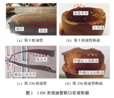
- The outer diameter was reduced by up to 13.98 mm, and wall thinning reached a maximum of 2.43 mm near the fracture.
- Fracture surfaces showed axial cracks, curling deformation, and features of secondary propagation.
236th Tubing:
- The upper tubing split longitudinally into two halves with a jagged fracture surface and spiral deformation.
- Transverse fractures near the external threads occurred, with one fracture near the large thread end and another 5 cm up the tubing body.
- Signs of curling plastic deformation were evident near the fractures.
Both fractures exhibited plastic deformation characteristics, confirming plastic fracture failure.
1.2 Mechanical and Chemical Properties
Samples were taken from the failed tubing sections and adjacent tubing for testing. Key findings included:
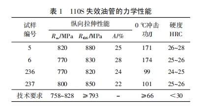
- Mechanical Properties:
- Tensile strength, impact resistance, and hardness met technical standards.

- Chemical Composition:
- The chemical composition of all samples complied with technical requirements.

- Metallurgical Properties:
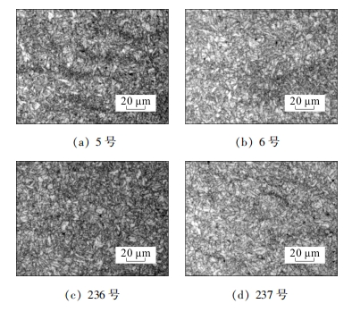
- The microstructure consisted of tempered sorbite with no abnormalities.
- Grain sizes were fine, with grades ranging from 10.5 to 10.9.
All test results confirmed that the tubing materials met the required specifications.
1.3 Fracture Surface and Corrosion Analysis
5th Tubing Fracture Surface:
- Upper Zone: Brittle failure with intergranular fracture features.
- Lower Zone: Plastic dimples (ductile failure), indicating tensile overload.
Corrosion Pits:
- Shallow pits were observed near the fractures.
- The largest pit on the 5th tubing was 130 μm deep, only 1.4% of the wall thickness.
- On the 236th tubing, pits had depths of 79–453 μm, occupying up to 7% of the wall thickness.
Corrosion Products:
- Analysis revealed a mix of oxides, sulfides, and chlorides, with minor amounts of iron sulfide.

1.4 Performance Testing
Destructive testing was conducted on tubing samples, including tensile, external pressure, and internal pressure tests. All results complied with technical agreement standards and confirmed that the tubing material was not the root cause of failure.
2. Discussion
2.1 Failure Mechanism
The primary failure mechanism was plastic fracture due to overload. This occurred when the tubing experienced tensile loads exceeding its ultimate tensile strength.
Key observations:
- Both the 5th and 236th tubing exhibited plastic deformation at failure, indicating high tensile stress at the time of fracture.
- The 236th tubing fractured first, triggering shock loads that caused the 5th tubing to yield and fail.
2.2 Sources of Tensile Load
The tensile load resulted from a combination of downhole factors:
- Packer Movement:
- Large pressure differentials caused the packer to shift, generating high axial tension in the tubing.
- Temperature-Induced Contraction:
- Rapid cooling during acidizing operations caused the tubing to contract, generating high tensile loads.
- Deformation Loads:
- Changes in the downhole fluid’s temperature and pressure caused deformation stresses, contributing to the tubing’s failure.
2.3 Corrosion Impact
Corrosion pits were present but shallow and did not significantly contribute to the failure. The failure was primarily caused by overload-induced plastic fracture, not corrosion.
3. Conclusions
The tubing failure was caused by plastic fracture due to excessive tensile loads. These loads exceeded the tubing’s ultimate tensile strength and were primarily caused by:
- Deformation stresses from changes in downhole fluid temperature and pressure.
- Large pressure differentials and rapid cooling during operations.
4. Recommendations
To prevent similar failures in the future, the following measures are recommended:
- Optimize Tubing Wall Thickness: Ensure sufficient strength to withstand high tensile loads.
- Adjust Packer Depth: Minimize axial tension caused by packer movement.
- Reassess Material and Specifications: Select materials and casing specifications suitable for extreme downhole conditions.
Key Takeaways
This case underscores the critical need to:
- Properly design and select tubing for ultra-deep wells.
- Monitor and manage operational parameters such as pressure, temperature, and packer performance to minimize tensile loads.
- Conduct comprehensive failure analyses to identify root causes and implement targeted solutions.
